
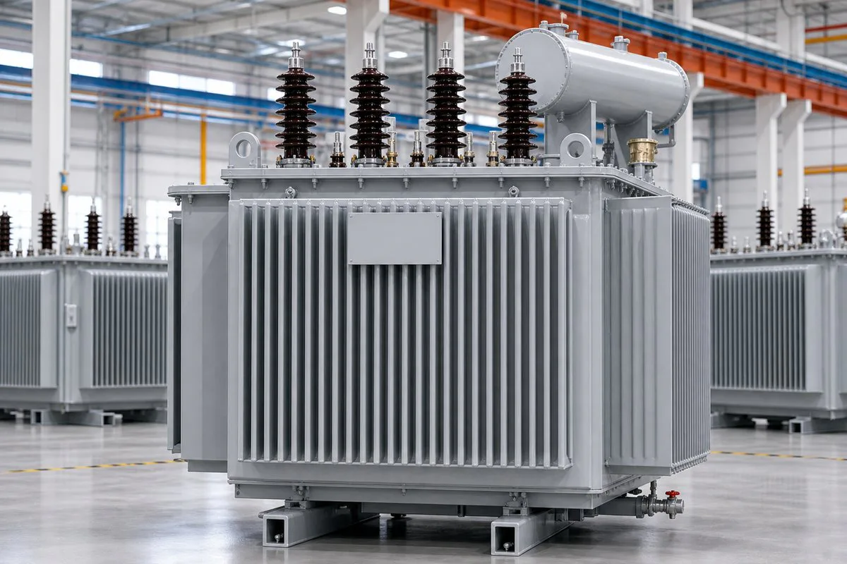
Amorphous Alloy Transformer Overview
Published three-phase references cover 30 to 3,000 kVA and 10 to 35 kV. Domestic product material states that no-load loss can be about 60% lower than a conventional oil-transformer reference; the exact comparison must use guaranteed values at the same rating.
The purchasing decision should compare total owning cost, guaranteed no-load and load losses, capitalization factors, sound level, footprint, short-circuit performance, tank structure, conductor, liquid, and the applicable S15, S21, or S25 series.
PRODUCT FITAmorphous Alloy Transformer: buyer-specific review points
For real procurement, Amorphous Alloy Transformer is judged by its project role, electrical boundary, verification documents, delivery condition, and the buyer's site limits before a factory quotation is compared.
Amorphous Alloy Transformer is mainly reviewed for Always-energized networks, Energy-efficiency programs, Renewable and industrial distribution. Amorphous-alloy oil-immersed transformers for distribution systems where energized hours and the cost of no-load losses justify a low-loss core design.
The first comparison should keep Phase: Three phase, Published capacity: 30-3,000 kVA, and Primary voltage: 10-35 kV visible so quotations remain technically comparable.
Published three-phase references cover 30 to 3,000 kVA and 10 to 35 kV. Domestic product material states that no-load loss can be about 60% lower than a conventional oil-transformer reference; the exact comparison must use. Confirm Core material: Amorphous-alloy wound core and Published series: S15 / S21 / S25 amorphous series before the data sheet is released.
For Amorphous Alloy Transformer, request documents such as Approved data sheet, GA and dimension drawing, Nameplate drawing, Routine test report, Inspection records. These files should match the ordered voltage class, rating, accessories, test plan, and nameplate.
Amorphous Alloy TransformerApplications
Utility and community transformers with long energized hours, where no-load losses accumulate throughout the year.
Grid upgrades and public projects with defined efficiency thresholds, evaluated losses, or lifecycle-cost criteria.
Auxiliary and local distribution where load profile, harmonic duty, losses, reliability, and outdoor service are reviewed together.
Amorphous Alloy TransformerPublished technical range
| Phase | Three phase |
|---|---|
| Published capacity | 30-3,000 kVA |
| Primary voltage | 10-35 kV |
| Core material | Amorphous-alloy wound core |
| Published series | S15 / S21 / S25 amorphous series |
| Construction | Hermetically sealed corrugated tank |
| Cooling | Oil natural / air natural (ONAN) |
| Windings | Copper or aluminum according to the approved design |
| Design basis | IEC 60076 or confirmed contract/project standard |
For Amorphous Alloy Transformer, Phase is referenced as Three phase. Amorphous Alloy Transformer The ordered value is fixed in the approved data sheet for the selected application.
For Amorphous Alloy Transformer, Published capacity is referenced as 30-3,000 kVA. Amorphous Alloy Transformer The ordered value is fixed in the approved data sheet for the selected application.
For Amorphous Alloy Transformer, Primary voltage is referenced as 10-35 kV. Amorphous Alloy Transformer The ordered value is fixed in the approved data sheet for the selected application.
Amorphous Alloy Transformer: the product scope follows the approved project specification. Published catalog values describe the available product family. Guaranteed values and included accessories are defined by the quotation and approved technical data sheet.
Amorphous Alloy TransformerConfiguration decisions
Compare no-load and load losses at the same kVA, voltage, impedance, temperature basis, conductor, and tolerance instead of relying only on a percentage claim.
Apply project energy price, energized hours, loading curve, capitalization factor, discount period, maintenance, and purchase price to the total-owning-cost comparison.
Confirm amorphous core construction, flux density, clamping, sound-power requirement, mechanical robustness, short-circuit duty, transport handling, and installation vibration.
Identify S15, S21, or S25 series, approved loss table, efficiency statement, core material reference, routine report, relevant type-test evidence, and final nameplate.
Amorphous Alloy TransformerManufacturing and verification
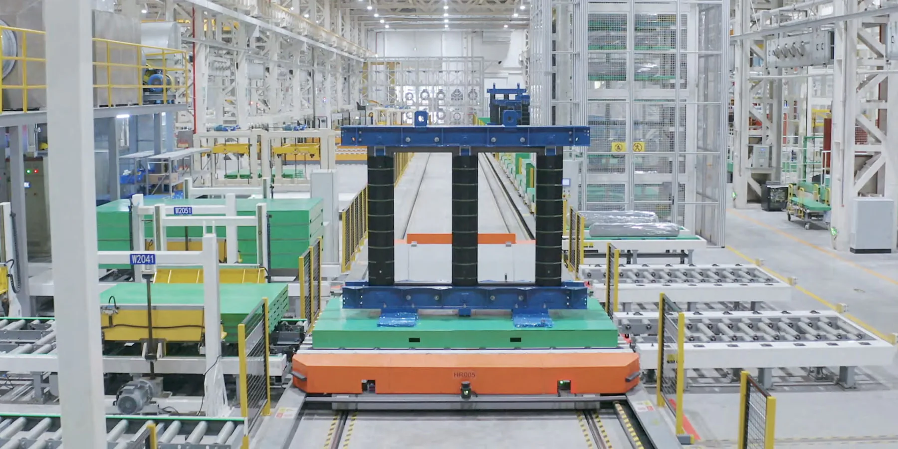
Core, conductor, insulation, leads, and clamping are built to the approved drawing, with in-process dimensional and connection checks.
The tank, radiators, valves, bushings, and seals are assembled and leak checked. The active part is dried, and insulating fluid is filtered and vacuum filled according to the design.
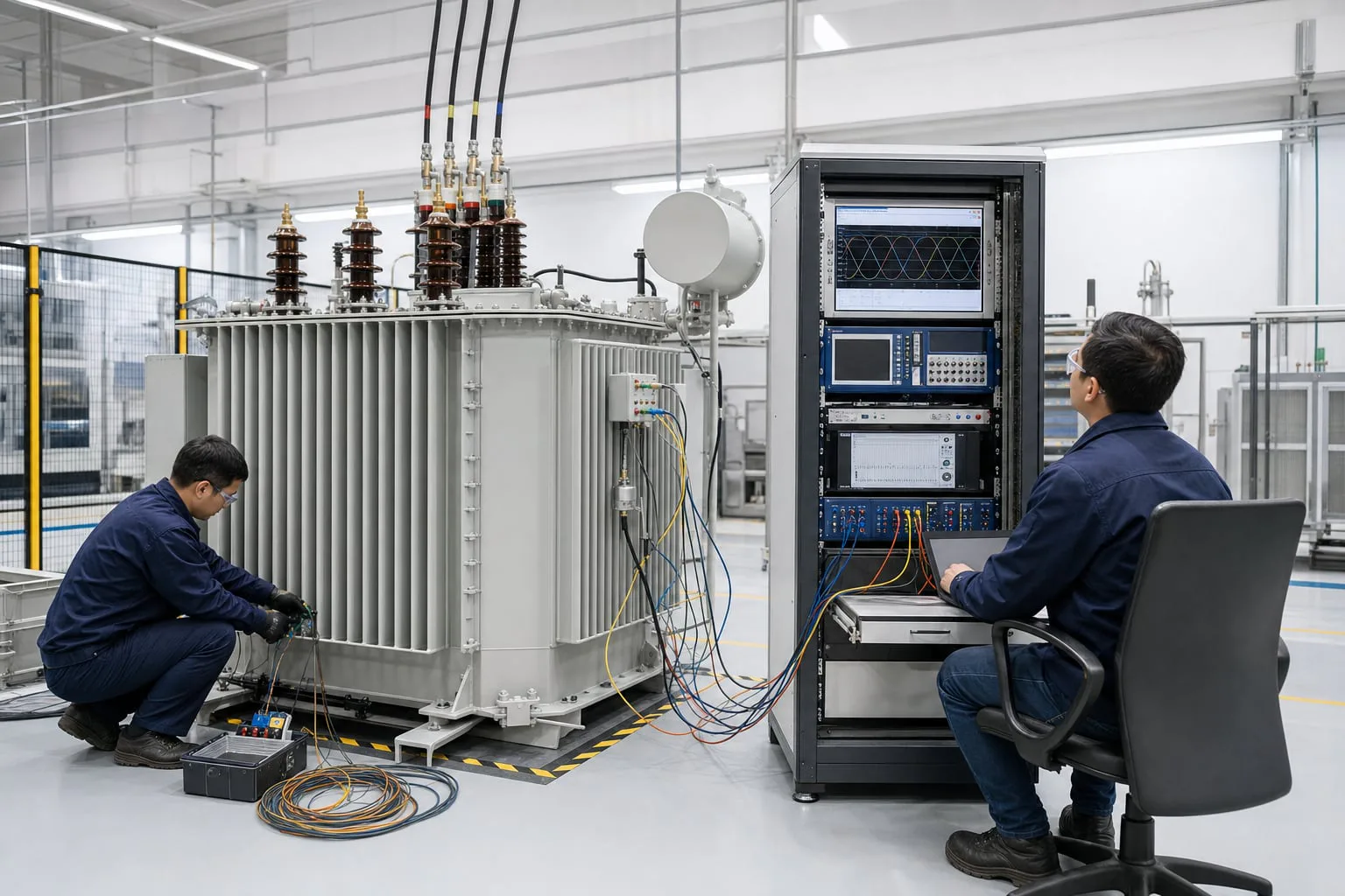
Ratio, vector group or polarity, winding resistance, insulation, no-load and load losses, impedance, withstand, and leak tests are completed to the approved standard and order scope.
Amorphous Alloy TransformerTesting and acceptance
Amorphous Alloy Transformer acceptance is planned around the approved product duty and Phase: Three phase, Published capacity: 30-3,000 kVA, Primary voltage: 10-35 kV, Core material: Amorphous-alloy wound core. Each test is tied to the ordered unit, nameplate data, and approved technical schedule.
Amorphous Alloy Transformer delivery preparation carries Primary voltage: 10-35 kV, Core material: Amorphous-alloy wound core, Published series: S15 / S21 / S25 amorphous series, Construction: Hermetically sealed corrugated tank into the approved drawing, accessory schedule, packing method, handling limits, and site interfaces.
Published series: S15 / S21 / S25 amorphous series. Approve the technical data sheet, GA drawing, nameplate, accessory schedule, test plan, and document list.
Construction: Hermetically sealed corrugated tank. Review routine-test records, visual inspection, leak condition, accessory completeness, preservation, and packing photographs.
Cooling: Oil natural / air natural (ONAN). Confirm lifting and jacking, removable parts, packing supports, container or break-bulk plan, shipping documents, and destination unloading.
Amorphous Alloy TransformerProject documents
Technical submittals are prepared around the approved transformer configuration so consultants, utilities, contractors, and inspectors can review the same controlled data.
FAT documentation and witness plan
For Amorphous Alloy Transformer, when FAT is required, the inspection scope, witness points, acceptance criteria and report package are confirmed against the approved specification before testing. The agreed plan follows the ordered rating and application.
Review the FAT process ↗Amorphous Alloy TransformerProject Configuration Checkpoints
Amorphous Alloy Transformer · Electrical boundary
Phase: Three phase and Published capacity: 30-3,000 kVA define the first comparison basis for Amorphous Alloy Transformer.
Amorphous Alloy Transformer · Engineering focus
The purchasing decision should compare total owning cost, guaranteed no-load and load losses, capitalization factors, sound level, footprint, short-circuit performance, tank structure, conductor, liquid, and the applicable S15, S21, or S25 series. Core material: Amorphous-alloy wound core and Published series: S15 / S21 / S25 amorphous series should be checked before drawing approval.
Amorphous Alloy Transformer · Acceptance files
Approved data sheet, GA and dimension drawing, Nameplate drawing, Routine test report must match the ordered model, rating, accessories, and test plan.
Amorphous Alloy TransformerTechnical FAQs
These Amorphous Alloy Transformer questions cover Phase: Three phase, Published capacity: 30-3,000 kVA, site duty, and Approved data sheet, GA and dimension drawing so buyers can judge model fit before sending an RFQ.
01How much can no-load loss be reduced?
The domestic product reference states about 60% lower no-load loss than a conventional oil-transformer design. The order comparison must use guaranteed values for the same rating and technical basis.
02Is an amorphous transformer always the lowest-cost choice?
Not necessarily. Purchase price, load profile, energy cost, energized hours, guaranteed load losses, space, sound, and project evaluation rules determine the economic result.
03Which series are published?
Published references include S15, S21, and S25 amorphous series. The exact loss table and efficiency requirement must be attached to the quotation.
04What test data should be compared?
Compare guaranteed and measured no-load loss, no-load current, load loss, impedance, ratio, winding resistance, dielectric tests, sound or temperature-rise data when required, and the applicable tolerance.
Amorphous Alloy Transformer Project Enquiry
Amorphous Alloy Transformer: Capacity, voltage, quantity, application, destination, site conditions, standard, drawings, and schedule are the main project inputs. The confirmed technical scope forms the basis for engineering response, drawings, testing, quotation, and delivery planning.