

Utility Grid Transformers Solution
Grid reinforcement, substation expansion, voltage transformation, and reliable distribution across changing utility loads. Main or distribution transformer, MV switchgear, protection, monitoring, and substation auxiliaries.

Utility Grid Transformers: project fit
Utility Grid Transformers is planned around the actual load, voltage system, installation space, protection interface, transformer construction, testing evidence, and handover documents.
Grid reinforcement, substation expansion, voltage transformation, and reliable distribution across changing utility loads. Confirm rating, voltage, load profile, overload margin, transformer type, and supply boundary around voltage regulation and loss guarantees. Convert voltage regulation and loss guarantees into verifiable equipment selection, ratings, operating limits, and reliability conditions.
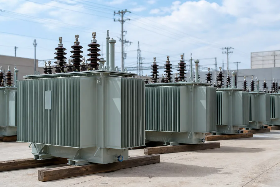
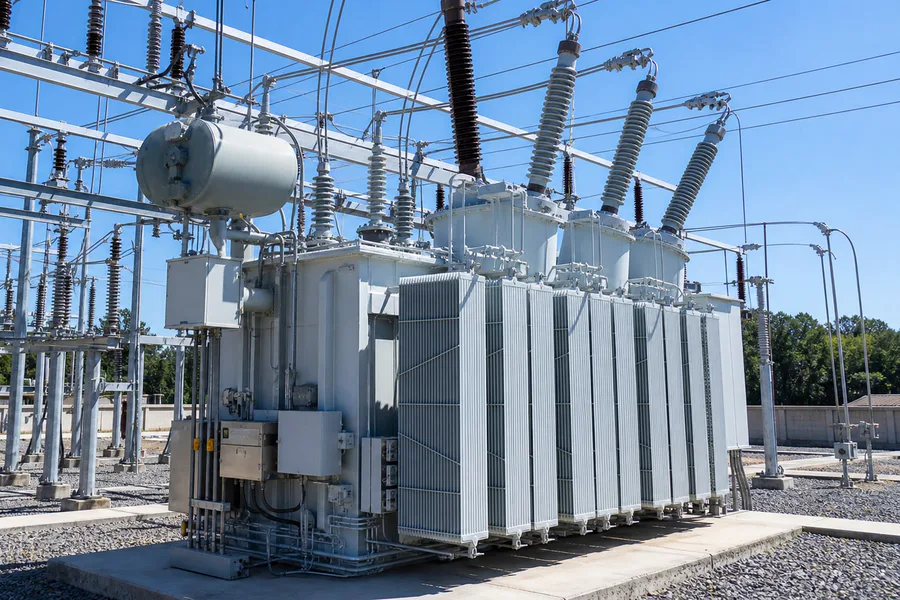
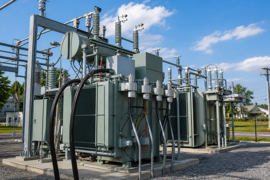
Use n-1 capacity and future load growth to select oil-immersed, dry-type, compact-substation, or special-transformer construction, then confirm cooling, enclosure, materials, and installation conditions. Related product families include 10-35kV Transformers, Power Transformers, Oil Immersed Transformers.
Carry protection, monitoring, and grid interfaces into monitoring, maintenance access, spares, acceptance, packing, transport, and later expansion planning. Use n-1 capacity and future load growth to confirm construction, materials, enclosure, cooling, installation conditions, and the related verification.
Main or distribution transformer, MV switchgear, protection, monitoring, and substation auxiliaries. The final package should stay consistent with the single-line diagram, installation space, reliability requirement, and destination documents. Evidence to review: Utility Grid Transformers load schedule and duty profile, Utility Grid Transformers single-line diagram and protection.
Use the Utility Grid Transformers load schedule and duty profile to confirm peaks, diversity, critical loads, redundancy, capacity growth, primary.
Translate voltage regulation and loss guarantees, fault duty and insulation coordination, and the remaining project priorities into equipment type.
Utility Grid Transformers load schedule and duty profile, Utility Grid Transformers single-line diagram and protection scheme, Utility Grid.
Utility Grid Transformers load and system priorities
Convert voltage regulation and loss guarantees into verifiable equipment selection, ratings, operating limits, and reliability conditions.
Define the design limits, system interfaces, equipment layout, and data-sheet requirements for fault duty and insulation coordination.
Use n-1 capacity and future load growth to confirm construction, materials, enclosure, cooling, installation conditions, and the related verification.
Carry protection, monitoring, and grid interfaces into drawings, maintenance access, monitoring, spares, acceptance, and future expansion planning.
Transformer Equipment for Utility Grid Transformers
These product families are directly relevant to the load profile, installation environment, and reliability requirements of Utility Grid Transformers. Final configuration follows the single-line diagram, site conditions, and project standard.
Utility Grid Transformers project design basis
| Voltage regulation and loss guarantees | Grid reinforcement, substation expansion, voltage transformation, and reliable distribution across changing utility loads. Confirm rating, voltage, load profile, overload margin, transformer type, and supply boundary around voltage regulation and loss guarantees. |
|---|---|
| Fault duty and insulation coordination | Convert fault duty and insulation coordination into transformer parameters, impedance, insulation, protection, accessories, upstream and downstream interfaces, and approved drawings. |
| N-1 capacity and future load growth | Use n-1 capacity and future load growth to select oil-immersed, dry-type, compact-substation, or special-transformer construction, then confirm cooling, enclosure, materials, and installation conditions. |
| Protection, monitoring, and grid interfaces | Carry protection, monitoring, and grid interfaces into monitoring, maintenance access, spares, acceptance, packing, transport, and later expansion planning. |
| Recommended equipment | Main or distribution transformer, MV switchgear, protection, monitoring, and substation auxiliaries. The final package should stay consistent with the single-line diagram, installation space, reliability requirement, and destination documents. |
Utility Grid Transformers engineering and delivery
Use the Utility Grid Transformers load schedule and duty profile to confirm peaks, diversity, critical loads, redundancy, capacity growth, primary and secondary voltage, and the supply boundary.
Translate voltage regulation and loss guarantees, fault duty and insulation coordination, and the remaining project priorities into equipment type, ratings, construction, losses, insulation, cooling, protection, layout, and system interfaces.
Control materials, production, assembly, and routine tests against the approved data sheet and drawings, with construction and temperature-rise checks for n-1 capacity and future load growth.
Complete FAT or inspection, packing, transport, and final-document handover, then confirm installation, maintenance, and expansion provisions for protection, monitoring, and grid interfaces.
Utility Grid Transformers technical files
Document scope for Utility Grid Transformers is confirmed against the exact product, ordered model, governing standard, and project document register.
Utility Grid Transformers technical questions
Which transformer configuration fits Utility Grid Transformers?
Main or distribution transformer, MV switchgear, protection, monitoring, and substation auxiliaries. Oil-immersed, dry-type, compact-substation, or special-transformer selection should follow voltage regulation and loss guarantees and fault duty and insulation coordination, then confirm rating, voltage, impedance, losses, and protection interface.
What should be prepared before quoting Utility Grid Transformers?
Send the load schedule or single-line diagram, primary and secondary voltage, quantity, installation environment, destination, and target delivery. If n-1 capacity and future load growth applies, include operating mode and maintenance limits.
Which site conditions change the transformer design?
Protection, monitoring, and grid interfaces can affect enclosure, protection, corrosion treatment, cooling, monitoring, transport dimensions, and maintenance access, so these points should appear in the data sheet and drawings.
Which quality files support a Utility Grid Transformers order?
The order package can include approved drawings, data sheet, nameplate file, component schedule, routine-test report, inspection records, packing records, and shipment files; FAT or third-party witness follows the project agreement.
Discuss your transformer project
Send the available capacity, voltage, quantity, destination, drawing, or specification for Utility Grid Transformers. We will confirm the equipment configuration, test documents, and delivery scope against the actual project.