
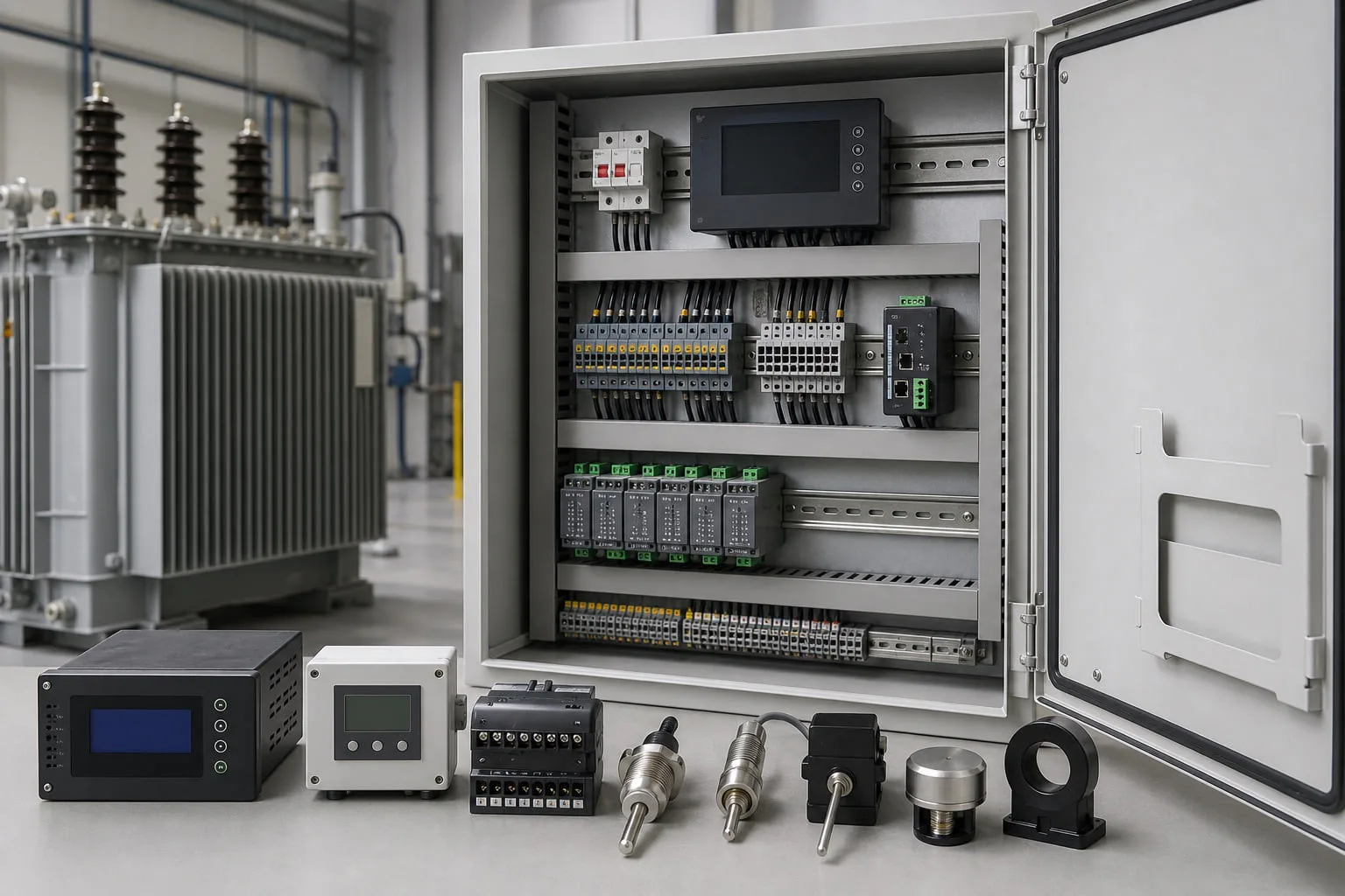
Transformer Monitoring System Overview
Transformer Monitoring System is configured for collecting transformer temperature, electrical, oil, gas, status, alarm, and accessory data for condition awareness.
For Transformer Monitoring System, the approved single-line diagram and data sheet convert collecting transformer temperature, electrical, oil, gas, status, alarm, and accessory data for condition awareness into defined ratings, interfaces, component scope, tests, dimensions, and delivery records.
A transformer monitoring system aggregates signals already available from the transformer and its accessories, such as winding and oil temperatures, oil level, gas relay, pressure, fan and pump status, tap position, alarms, and selected electrical quantities.
The project point list defines sensor ownership, analog ranges, dry contacts, transducers, sampling, alarm thresholds, local display, event records, RS485 or Ethernet interfaces, protocol map, time synchronization, and SCADA gateway boundary.
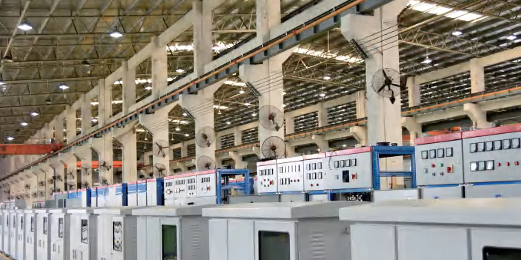
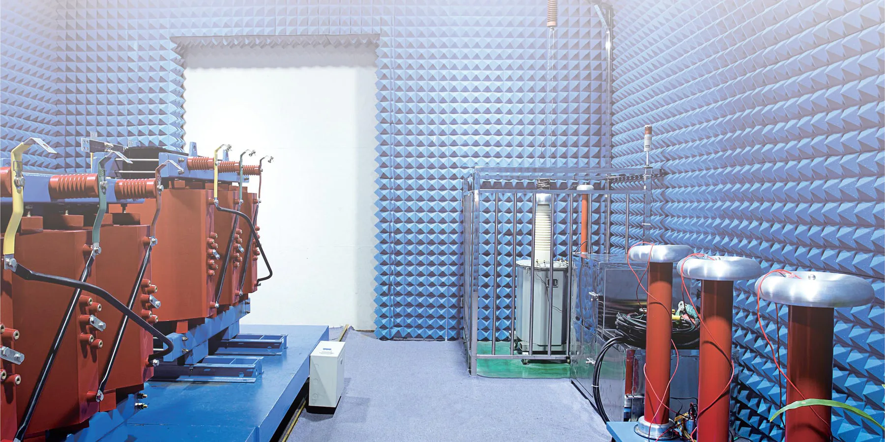
PRODUCT FITTransformer Monitoring System: buyer-specific review points
For real procurement, Transformer Monitoring System is judged by its project role, electrical boundary, verification documents, delivery condition, and the buyer's site limits before a factory quotation is compared.
Transformer Monitoring System is mainly reviewed for transformer condition monitoring, utility grid, industrial plant. collecting transformer temperature, electrical, oil, gas, status, alarm, and accessory data for condition awareness
The first comparison should keep Measurement scope: Temperature, electrical quantities, status, alarm, and accessory signals as specified, Sensor scope: Selected from temperature, oil level, gas, partial discharge, environment, door, and water sensors, and Communication protocol: RS485 / Modbus-class interface; final map confirmed visible so quotations remain technically comparable.
Transformer Monitoring System is configured for collecting transformer temperature, electrical, oil, gas, status, alarm, and accessory data for condition awareness. Confirm System arrangement: Transformer Monitoring System arrangement coordinated with the single-line diagram and Monitoring and communication: Transformer Monitoring System monitoring points selected for the protection and maintenance plan before the data sheet is released.
For Transformer Monitoring System, request documents such as Approved data sheet for Transformer Monitoring System, General arrangement drawing for Transformer Monitoring System, Single-line and schematic diagrams for Transformer Monitoring System, Interface and terminal drawings for Transformer Monitoring System, Bill of materials or component schedule for Transformer Monitoring System. These files should match the ordered voltage class, rating, accessories, test plan, and nameplate.
Transformer Monitoring System engineering focus
A transformer monitoring system aggregates signals already available from the transformer and its accessories, such as winding and oil temperatures, oil level, gas relay, pressure, fan and pump status, tap position, alarms, and selected electrical quantities.
The project point list defines sensor ownership, analog ranges, dry contacts, transducers, sampling, alarm thresholds, local display, event records, RS485 or Ethernet interfaces, protocol map, time synchronization, and SCADA gateway boundary.
Panel engineering covers auxiliary supply, isolation, surge protection, terminals, earthing, EMC, environmental rating, cable schedule, marshalling, fail-safe behavior, cybersecurity requirements where specified, and maintainable replacement of modules.
FAT verifies each input and output, scaling, alarm and trip logic, display, event record, communication register, loss-of-signal behavior, control permissions, wiring drawings, point list, and integration documentation.
Transformer Monitoring System should be checked against Measurement scope: Temperature, electrical quantities, status, alarm, and accessory signals as specified, Sensor scope: Selected from temperature, oil level, gas, partial discharge, environment, door, and water sensors, and transformer condition monitoring before the factory price is treated as comparable.
The quotation boundary for Transformer Monitoring System must keep Monitoring and communication: Transformer Monitoring System monitoring points selected for the protection and maintenance plan, Enclosure and protection: Transformer Monitoring System enclosure selected for indoor, outdoor, IP, and corrosion conditions, accessories, packing, and commissioning support visible to the buyer.
For Transformer Monitoring System, the document package should connect Design and test basis: Transformer Monitoring System design and tests set by the project standard and destination, Measurement scope: Temperature, electrical quantities, status, alarm, and accessory signals as specified, the nameplate, routine-test report, and approved drawing revision.
Transformer Monitoring System delivery planning should review transport size, lifting points, cable direction, site access, storage condition, and destination-specific documents.
Transformer Monitoring SystemApplications
Transformer Monitoring System is selected for transformer condition monitoring. A transformer monitoring system aggregates signals already available from the transformer and its accessories, such as winding and oil temperatures, oil level, gas relay, pressure, fan and pump status, tap position, alarms, and selected electrical quantities. The project review confirms Measurement scope: Temperature, electrical quantities, status, alarm, and accessory signals as specified and Communication protocol: RS485 / Modbus-class interface; final map confirmed against the actual system and site.
Transformer Monitoring System is selected for utility grid. The project point list defines sensor ownership, analog ranges, dry contacts, transducers, sampling, alarm thresholds, local display, event records, RS485 or Ethernet interfaces, protocol map, time synchronization, and SCADA gateway boundary. The project review confirms Sensor scope: Selected from temperature, oil level, gas, partial discharge, environment, door, and water sensors and System arrangement: Transformer Monitoring System arrangement coordinated with the single-line diagram against the actual system and site.
Transformer Monitoring System is selected for industrial plant. Panel engineering covers auxiliary supply, isolation, surge protection, terminals, earthing, EMC, environmental rating, cable schedule, marshalling, fail-safe behavior, cybersecurity requirements where specified, and maintainable replacement of modules. The project review confirms Communication protocol: RS485 / Modbus-class interface; final map confirmed and Monitoring and communication: Transformer Monitoring System monitoring points selected for the protection and maintenance plan against the actual system and site.
Transformer Monitoring SystemPublished technical reference
| Measurement scope | Temperature, electrical quantities, status, alarm, and accessory signals as specified |
|---|---|
| Sensor scope | Selected from temperature, oil level, gas, partial discharge, environment, door, and water sensors |
| Communication protocol | RS485 / Modbus-class interface; final map confirmed |
| System arrangement | Transformer Monitoring System arrangement coordinated with the single-line diagram |
| Monitoring and communication | Transformer Monitoring System monitoring points selected for the protection and maintenance plan |
| Enclosure and protection | Transformer Monitoring System enclosure selected for indoor, outdoor, IP, and corrosion conditions |
| Design and test basis | Transformer Monitoring System design and tests set by the project standard and destination |
For Transformer Monitoring System, Measurement scope is referenced as Temperature, electrical quantities, status, alarm, and accessory signals as specified. FAT verifies each input and output, scaling, alarm and trip logic, display, event record, communication register, loss-of-signal behavior, control permissions, wiring drawings, point list, and integration documentation. The ordered value is fixed in the approved data sheet for the selected application.
For Transformer Monitoring System, Sensor scope is referenced as Selected from temperature, oil level, gas, partial discharge, environment, door, and water sensors. Transformer Monitoring System delivery planning should review transport size, lifting points, cable direction, site access, storage condition, and destination-specific documents. The ordered value is fixed in the approved data sheet for the selected application.
For Transformer Monitoring System, Communication protocol is referenced as RS485 / Modbus-class interface; final map confirmed. Transformer Monitoring System is configured for collecting transformer temperature, electrical, oil, gas, status, alarm, and accessory data for condition awareness. The ordered value is fixed in the approved data sheet for the selected application.
Transformer Monitoring System: collecting transformer temperature, electrical, oil, gas, status, alarm, and accessory data for condition awareness. Published values identify catalog platforms or reference configurations. Final ratings, component brands, withstand levels, dimensions, losses, temperatures, protocols, and guarantees follow the approved project data sheet.
Transformer Monitoring SystemConfiguration priorities
For Transformer Monitoring System, evaluate this decision against collecting transformer temperature, electrical, oil, gas, status, alarm, and accessory data for condition awareness, Measurement scope: Temperature, electrical quantities, status, alarm, and accessory signals as specified, and the transformer condition monitoring operating duty. A transformer monitoring system aggregates signals already available from the transformer and its accessories, such as winding and oil temperatures, oil level, gas relay, pressure, fan and pump status, tap position, alarms, and selected electrical quantities.
For Transformer Monitoring System, evaluate this decision against collecting transformer temperature, electrical, oil, gas, status, alarm, and accessory data for condition awareness, Sensor scope: Selected from temperature, oil level, gas, partial discharge, environment, door, and water sensors, and the utility grid operating duty. The project point list defines sensor ownership, analog ranges, dry contacts, transducers, sampling, alarm thresholds, local display, event records, RS485 or Ethernet interfaces, protocol map, time synchronization, and SCADA gateway boundary.
For Transformer Monitoring System, evaluate this decision against collecting transformer temperature, electrical, oil, gas, status, alarm, and accessory data for condition awareness, Communication protocol: RS485 / Modbus-class interface; final map confirmed, and the industrial plant operating duty. Panel engineering covers auxiliary supply, isolation, surge protection, terminals, earthing, EMC, environmental rating, cable schedule, marshalling, fail-safe behavior, cybersecurity requirements where specified, and maintainable replacement of modules.
For Transformer Monitoring System, evaluate this decision against collecting transformer temperature, electrical, oil, gas, status, alarm, and accessory data for condition awareness, System arrangement: Transformer Monitoring System arrangement coordinated with the single-line diagram, and the smart distribution network operating duty. FAT verifies each input and output, scaling, alarm and trip logic, display, event record, communication register, loss-of-signal behavior, control permissions, wiring drawings, point list, and integration documentation.
Transformer Monitoring SystemEngineering, assembly, and verification
For Transformer Monitoring System, this stage is controlled against collecting transformer temperature, electrical, oil, gas, status, alarm, and accessory data for condition awareness and Sensor scope: Selected from temperature, oil level, gas, partial discharge, environment, door, and water sensors. The project point list defines sensor ownership, analog ranges, dry contacts, transducers, sampling, alarm thresholds, local display, event records, RS485 or Ethernet interfaces, protocol map, time synchronization, and SCADA gateway boundary.
For Transformer Monitoring System, this stage is controlled against collecting transformer temperature, electrical, oil, gas, status, alarm, and accessory data for condition awareness and Communication protocol: RS485 / Modbus-class interface; final map confirmed. Panel engineering covers auxiliary supply, isolation, surge protection, terminals, earthing, EMC, environmental rating, cable schedule, marshalling, fail-safe behavior, cybersecurity requirements where specified, and maintainable replacement of modules.
For Transformer Monitoring System, this stage is controlled against collecting transformer temperature, electrical, oil, gas, status, alarm, and accessory data for condition awareness and System arrangement: Transformer Monitoring System arrangement coordinated with the single-line diagram. FAT verifies each input and output, scaling, alarm and trip logic, display, event record, communication register, loss-of-signal behavior, control permissions, wiring drawings, point list, and integration documentation.
Transformer Monitoring SystemProject technical documents
Transformer Monitoring System: Project technical documents The document set remains linked to collecting transformer temperature, electrical, oil, gas, status, alarm, and accessory data for condition awareness and the approved product configuration. The final configuration is confirmed against the single-line diagram, load or duty profile, site conditions, applicable standard, interface drawings, testing plan, and document schedule.
FAT documentation and witness plan
For Transformer Monitoring System, when FAT is required, the inspection scope, witness points, acceptance criteria and report package are confirmed against the approved specification before testing. The agreed plan follows collecting transformer temperature, electrical, oil, gas, status, alarm, and accessory data for condition awareness.
Review the FAT process ↗Transformer Monitoring SystemProject Configuration Checkpoints
Transformer Monitoring System · Electrical boundary
Measurement scope: Temperature, electrical quantities, status, alarm, and accessory signals as specified and Sensor scope: Selected from temperature, oil level, gas, partial discharge, environment, door, and water sensors define the first comparison basis for Transformer Monitoring System.
Transformer Monitoring System · Engineering focus
A transformer monitoring system aggregates signals already available from the transformer and its accessories, such as winding and oil temperatures, oil level, gas relay, pressure, fan and pump status, tap position, alarms, and selected electrical quantities. System arrangement: Transformer Monitoring System arrangement coordinated with the single-line diagram and Monitoring and communication: Transformer Monitoring System monitoring points selected for the protection and maintenance plan should be checked before drawing approval.
Transformer Monitoring System · Acceptance files
Approved data sheet for Transformer Monitoring System, General arrangement drawing for Transformer Monitoring System, Single-line and schematic diagrams for Transformer Monitoring System, Interface and terminal drawings for Transformer Monitoring System must match the ordered model, rating, accessories, and test plan.
Transformer Monitoring SystemTechnical FAQs
These Transformer Monitoring System questions cover Measurement scope: Temperature, electrical quantities, status, alarm, and accessory signals as specified, Sensor scope: Selected from temperature, oil level, gas, partial discharge, environment, door, and water sensors, site duty, and Approved data sheet for Transformer Monitoring System, General arrangement drawing for Transformer Monitoring System so buyers can judge model fit before sending an RFQ.
01What technical range is published for Transformer Monitoring System?
Transformer Monitoring System: Measurement scope: Temperature, electrical quantities, status, alarm, and accessory signals as specified; Sensor scope: Selected from temperature, oil level, gas, partial discharge, environment, door, and water sensors; Communication protocol: RS485 / Modbus-class interface; final map confirmed; System arrangement: Transformer Monitoring System arrangement coordinated with the single-line diagram. A transformer monitoring system aggregates signals already available from the transformer and its accessories, such as winding and oil temperatures, oil level, gas relay, pressure, fan and pump status, tap position, alarms, and selected electrical quantities.
02How is Transformer Monitoring System configured for a project?
Transformer Monitoring System: The project point list defines sensor ownership, analog ranges, dry contacts, transducers, sampling, alarm thresholds, local display, event records, RS485 or Ethernet interfaces, protocol map, time synchronization, and SCADA gateway boundary. Monitoring and communication: Transformer Monitoring System monitoring points selected for the protection and maintenance plan; Enclosure and protection: Transformer Monitoring System enclosure selected for indoor, outdoor, IP, and corrosion conditions; Design and test basis: Transformer Monitoring System design and tests set by the project standard and destination.
03Which documents accompany Transformer Monitoring System?
Transformer Monitoring System documents should identify Sensor scope: Selected from temperature, oil level, gas, partial discharge, environment, door, and water sensors; Communication protocol: RS485 / Modbus-class interface; final map confirmed; System arrangement: Transformer Monitoring System arrangement coordinated with the single-line diagram; Monitoring and communication: Transformer Monitoring System monitoring points selected for the protection and maintenance plan and include Approved data sheet, General arrangement drawing, Single-line and schematic diagrams, Interface and terminal drawings for the ordered unit.
04What should be sent for a Transformer Monitoring System quotation?
Transformer Monitoring System: FAT verifies each input and output, scaling, alarm and trip logic, display, event record, communication register, loss-of-signal behavior, control permissions, wiring drawings, point list, and integration documentation. Send Measurement scope: Temperature, electrical quantities, status, alarm, and accessory signals as specified; Sensor scope: Selected from temperature, oil level, gas, partial discharge, environment, door, and water sensors; Communication protocol: RS485 / Modbus-class interface; final map confirmed; System arrangement: Transformer Monitoring System arrangement coordinated with the single-line diagram, quantity, destination, site conditions, drawings, inspection needs, and target delivery date.
Transformer Monitoring System Project Enquiry
Transformer Monitoring System: Capacity, voltage, quantity, application, destination, site conditions, standard, drawings, and schedule are the main project inputs. The confirmed technical scope forms the basis for engineering response, drawings, testing, quotation, and delivery planning.